ISO 9001 API 6D CE / PED EN

Support · Torque & Gearbox Sizing

Torque Selection Guide for Valve Gear Operators — How to Select the Correct Torque for Worm Gear Operators and Valve Gearboxes

Selecting the correct torque is one of the most important steps when choosing a valve gear operator or worm gear gearbox. Undersized equipment may fail to move the valve under real process conditions; oversized units add unnecessary cost, weight, and inertia without improving reliability. This torque selection guide explains valve operating torque, breakaway and seating requirements, safety factor methodology, and practical gearbox torque selection for quarter-turn and multi-turn valves — with links to our torque-based selection tools and engineering support for project verification.

Breakaway & Run Torque Safety Factor Tables Gearbox Sizing Examples

Engineering Fundamentals

Why Torque Selection Matters

Torque is the rotational force required to operate a valve — to overcome static friction, process pressure loads, seal compression, and media effects. Every isolation, control, or block valve in industrial service demands a specific operating torque profile across its stroke. If the gearbox output torque is insufficient, the valve may not reach its intended position, leading to process upsets, incomplete isolation, or emergency shutdown failures. Conversely, gross oversizing increases handwheel effort perception, actuator cost, and mounting loads without benefit. Proper torque selection and gearbox torque selection support reliable operation, improved safety margins, reduced mechanical wear, extended equipment life, and smoother actuator integration when automation is added later.

  • Reliable operation — gear operators deliver consistent break-to-open and seating performance under rated process conditions.
  • Improved safety — adequate torque margins protect personnel and assets when valves must close under differential pressure.
  • Reduced wear — correctly sized worm sets and stem interfaces avoid chronic overstress and premature component failure.
  • Extended equipment life — matching gearbox rating to actual valve torque reduces heat, backlash growth, and lubricant breakdown.
  • Actuator compatibility — manual gearboxes sized with future electric, pneumatic, or hydraulic actuators in mind simplify upgrades and ISO 5211 mounting integration.

Torque Definitions

What Is Valve Operating Torque?

Valve operating torque is the rotational force — typically expressed in newton-metres (Nm) or foot-pounds (ft·lb) — required to move a valve through its stroke under defined process conditions. Unlike a static load rating stamped on a nameplate, operating torque varies with position: initiating movement from rest demands more effort than maintaining motion mid-stroke, and closing against differential pressure often exceeds opening torque. Gearbox torque selection and worm gear operator sizing therefore begin by identifying the highest torque the valve presents during its duty cycle, not an average or nominal catalogue value. Understanding the four primary torque phases below is essential before applying safety factors or comparing datasheet ratings from valve and gearbox suppliers.

Breakaway Torque

Breakaway torque — also called break-to-open or starting torque — is usually the highest value in the operating profile. It is the force needed to overcome static friction, settled media, hardened deposits, and initial seal compression after the valve has remained stationary. Gear operators and actuators must be sized to break the valve free reliably; undersizing at this point is the most common cause of failed manual operation and stalled automation in the field.

Running Torque

Running torque applies while the valve disc, ball, plug, or gate is in motion between open and closed positions. It is generally lower than breakaway torque because dynamic friction and hydrodynamic effects differ from static conditions. For modulating service, running torque may still vary with flow-induced loads — but peak running values rarely govern gearbox selection unless the valve operates continuously under high differential pressure.

Seating Torque

Seating torque is the force required to move the valve into its fully closed position and achieve the designed seal compression. On butterfly, ball, and plug valves, seating often coincides with the highest torque in the close direction because the seal must deform against the seat ring under process pressure. For isolation valves in critical service, seating torque frequently defines the minimum gearbox output rating when closing against full differential pressure.

Unseating Torque

Unseating torque is the force needed to open a valve that has been closed long enough for seals to set, process pressure to load the closure member, or media to bond contact surfaces. It can exceed breakaway torque on high-pressure ball valves and plug valves where the closed position traps pressure upstream of the seat. Projects planning infrequent operation — emergency shutdown valves, spare isolation, or seasonal process lines — should always evaluate unseating torque, not only first-time commissioning values.

Application Variables

Factors Affecting Valve Torque

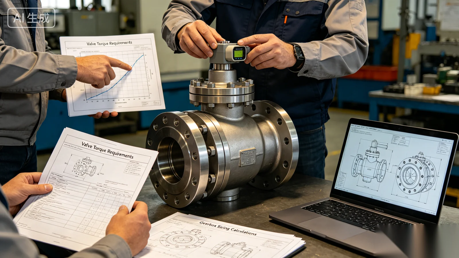
Valve torque is never determined by valve size alone. The same nominal diameter can require dramatically different gearbox ratings depending on valve type, pressure class, media characteristics, temperature, and how often the valve cycles. Process engineers and procurement teams who rely solely on catalogue torque tables without application context risk undersized gear operators that fail on first high-pressure close, or oversized units that add cost without reliability benefit. The following factors interact in every valve torque calculation and gearbox torque selection exercise — use them systematically when reviewing vendor data, building a torque-based equipment shortlist, or submitting valves for factory engineering review.

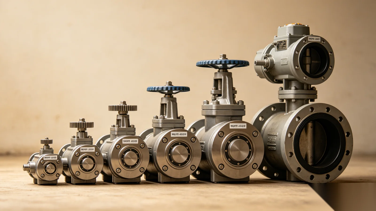
Valve size influences torque through increased disc or ball surface area, larger stem diameter, and greater seal contact length. As bore diameter grows, friction loads and hydrodynamic forces scale non-linearly — a 600 mm butterfly valve is not simply twice the torque of a 300 mm unit at the same pressure rating. Always request torque curves or test data at the actual valve size, not interpolated values from a smaller bore in the same product family.

Operating pressure and differential pressure across the closure member directly affect breakaway, seating, and unseating torque. A valve closing against full line pressure traps load on the seat; opening against differential can require substantial force to relieve that load before motion begins. High-pressure ball and plug valves in isolation service are particularly sensitive — torque can increase by 50% or more compared to low-pressure laboratory test conditions.

Process media changes friction and deposit behaviour over time. Clean water and air impose moderate, predictable loads; slurry, pulp, bitumen, and crystallizing chemicals raise breakaway torque as solids pack around the closure member. Viscous oils and polymerizing fluids increase running torque. Corrosive media may degrade seals and seats, gradually increasing torque beyond original commissioning baselines — a maintenance consideration as much as a sizing input.

Temperature affects seal material modulus, lubricant viscosity in the valve and gearbox, and thermal expansion of stem and body components. Cryogenic service stiffens elastomer seals; elevated steam or thermal oil temperatures soften PTFE and graphite packings, sometimes reducing breakaway torque initially but accelerating wear. Gearbox lubricant selection must match the installation environment so that worm set efficiency does not degrade under extreme heat or cold.

Operating frequency influences whether peak torque or cumulative wear governs design. Valves cycled hourly in modulating control may never experience maximum static set — yet frequent partial stroke operation wears seats unevenly. Rarely operated block valves face maximum unseating challenge after months or years stationary. Safety factors and material choices should reflect duty class, not only instantaneous torque peaks.

Torque Characteristics by Valve Type

Butterfly Valves

Moderate torque profiles dominated by disc seal friction and shaft bearing loads. Torque typically peaks at or near the seated position. Common in water treatment, HVAC, and general process isolation from DN50 to very large diameters.

Ball Valves

Higher breakaway and unseating torque due to floating or trunnion seat design and trapped-cavity pressure effects. Full-bore and reduced-bore variants differ significantly — always confirm bore type on datasheets.

Plug Valves

Elevated torque from metal-to-metal or sleeved plug sealing friction, especially in lubricated and non-lubricated designs. Sizing must account for long idle periods in pipeline block valve service.

Gate Valves

Multi-turn rising-stem designs where thrust and number of turns matter alongside torque. Wedge gate seating against pressure generates high closing loads; gearbox selection pairs torque with stem thread pitch and travel.

Globe Valves

Multi-turn linear motion with sustained stem packing friction through travel. Modulating applications may require lower ratio gearboxes for resolution; isolation duty may prioritize maximum thrust capacity.

Knife Gate Valves

Slurry and pulp service with abrasive media packing the gate path. Breakaway torque can spike when solids consolidate; heavy-duty safety factors and corrosion-resistant gear operators are standard practice.

Reference Data

Typical Valve Torque Ranges

The table below summarizes indicative torque ranges encountered in industrial valve applications. These values support early budgeting and preliminary gearbox torque selection — they are not substitutes for manufacturer test data, project-specific calculations, or engineering sign-off on critical isolation valves.

Important: The following values are examples only. Actual torque requirements should always be verified with valve manufacturer data, bench testing where available, and application of appropriate safety factors before procurement.

Valve Type Typical Torque Range
Small Butterfly Valve50–500 Nm
Medium Butterfly Valve500–2,000 Nm
Large Butterfly Valve2,000–20,000+ Nm
Ball Valve100–10,000+ Nm
Plug Valve200–15,000+ Nm
Gate ValveApplication-specific (multi-turn; consult thrust and torque data)
Globe ValveApplication-specific (multi-turn; consult thrust and torque data)

Sizing Methodology

How to Calculate Required Gearbox Torque

Gearbox torque selection follows a straightforward principle: identify the maximum valve operating torque expected in service — usually breakaway, seating, or unseating, whichever is highest — then multiply by a project-appropriate safety factor. The safety factor accounts for measurement uncertainty, media variation, seal wear, temperature effects, and the mechanical efficiency losses between the gearbox output and the valve stem. Never size a worm gear operator to match valve torque exactly; margin is not optional in industrial isolation and control applications.

Trequired = Tvalve × Safety Factor

Where Tvalve is the maximum documented operating torque (Nm) from the valve supplier or test record, and Safety Factor is selected from project standards or the table below. Apply the factor to the governing torque value — not to run torque alone if breakaway exceeds it. For automated systems, confirm that actuator rated torque also meets Trequired after efficiency and duty-cycle derating.

Application Typical Safety Factor
Clean Water Service1.25 – 1.5
Industrial Utilities1.5
Chemical Processing1.5 – 2.0
Mining Applications2.0
Offshore Applications2.0
Critical Isolation Valves2.0+

Worked example: A large butterfly valve in water treatment service has a manufacturer-stated maximum operating torque of 2,000 Nm. The project specifies a 1.5 safety factor for clean water duty. Required gearbox output torque: 2,000 Nm × 1.5 = 3,000 Nm minimum. Select a worm gear operator rated at or above 3,000 Nm output with compatible mounting interface — verify ISO 5211 flange and drive geometry separately from torque rating.

Engineer calculating required gearbox torque from valve operating torque and safety factor
T × SF Gearbox torque sizing

Product Matching

Selecting Gear Operators by Torque

Once required output torque is calculated, map the value to a gear operator product class with adequate rating, correct motion type (quarter-turn or multi-turn), and mounting interface compatible with the valve top flange. ValveWormGear manufactures worm gear operators across the full industrial torque spectrum — from compact utility units to heavy-duty pipeline and hydropower gearboxes. Use our torque-based selection tools to filter models by output rating, or submit valve datasheets for application engineering confirmation.

Low Torque Applications (50–500 Nm)

Small butterfly valves, building services isolation, HVAC balancing, and light-duty utility automation. Compact worm gear operators with F03–F05 class mounting interfaces are typical. Suitable for manual operation and small electric actuators.

Medium Torque Applications (500–3,000 Nm)

Water treatment isolation, general chemical process block valves, and standard industrial automation. F07–F10 ISO 5211 mounts predominate. This range represents the highest-volume segment in municipal and manufacturing projects.

High Torque Applications (3,000–10,000 Nm)

Large butterfly and ball valves, pipeline block valves, and power generation auxiliary systems. Requires robust worm sets, larger handwheels, and reinforced housings. Browse our worm gear operator range for rated models in this class.

Heavy-duty Applications (10,000+ Nm)

Hydropower penstock valves, mining slurry isolation, offshore pipeline ESD, and large process block valves. Custom ratios, special materials, and extended bearing spans are common — contact engineering for project-specific proposals.

Worm gear operators arranged by torque rating for valve gearbox selection
By Torque Gear operator families

Motion Classes

Quarter-turn vs Multi-turn Torque Selection

Valve motion class determines how operating torque translates into gearbox specification. Quarter-turn and multi-turn systems use different mechanical principles — conflating the two leads to incorrect product selection even when torque numbers appear similar on paper.

Quarter-turn Valves

Butterfly, ball, and plug valves rotate approximately 90° between open and closed positions. Torque is the primary sizing parameter for worm gear operators and actuators: output torque at the stem must exceed Trequired throughout the stroke, with particular attention to seating and unseating peaks.

  • Single-stage worm gear common; ratio defines handwheel turns per 90°
  • ISO 5211 mounting standard applies to most industrial sizes
  • Electric and pneumatic actuators sized directly on torque output
  • Self-locking worm geometry holds position without continuous input

Multi-turn Valves

Gate, globe, and knife gate valves use rising stems requiring many handwheel revolutions. Selection considers operating torque, axial thrust, stem thread pitch, total travel, and number of turns — not torque alone. High-ratio worm gearboxes convert handwheel rotation into linear stem motion through the valve yoke or bonnet thread.

  • Thrust capacity must support stem load under maximum differential pressure
  • Gear ratio affects operating time — critical for large gate valves
  • Stem nut wear and lubrication influence long-term torque growth
  • Automation may require multi-turn electric actuators with thrust rating

Actuator Integration

Torque Selection for Automated Systems

When electric, pneumatic, or hydraulic actuators replace or supplement manual worm gear operators, torque selection expands beyond valve breakaway values to include actuator performance curves, duty cycles, and fail-safe behaviour. A gearbox rated for comfortable handwheel operation may still be inadequate as the mechanical interface for an actuator producing higher dynamic loads during stall or end-position seating. Plan automation during initial gearbox selection — retrofitting actuators on undersized manual gearboxes is costly and often mechanically impossible without valve modification. Coordinate valve torque data, gearbox rating, actuator catalogue values, and ISO 5211 mounting compatibility in a single submittal package for EPC review.

Electric Actuators

Size on rated output torque with safety factor applied to valve break torque — typically 1.25 to 1.5 minimum for on/off duty. Evaluate starting torque, stall torque, and duty class (S2, S4, etc.) for modulating applications where the motor runs frequently at partial stroke. Confirm that maximum actuator torque does not exceed gearbox or valve stem mechanical limits. End-position torque limiting and motor thermal protection are essential on high-pressure seating applications.

Pneumatic Actuators

Torque output varies with supply air pressure — size at minimum guaranteed plant air pressure, not nominal 6 bar only. Review manufacturer torque curves at 4, 5, and 6 bar. Spring-return fail-safe units must generate adequate torque in the fail direction under degraded pressure conditions. Scotch-yoke designs produce torque that changes with angle; rack-and-pinion units offer more uniform profiles. Match actuator type to valve torque curve shape.

Hydraulic Actuators

Hydraulic systems deliver high force in compact envelopes — common on large pipeline and subsea valves. Size from available hydraulic pressure, cylinder bore, and lever arm geometry. Operating speed and shock loading during rapid stroke completion can exceed steady-state torque calculations; include dynamic factors in critical ESD applications. Integrate with gearbox only where declutchable or combined units are specified by design.

Industry Duty

Environmental Considerations for Torque Selection

Installation environment influences both the torque safety factor and the physical specification of the gear operator housing, coatings, and lubricants. Industry-specific duty conditions below are typical starting points — always confirm with site standards and regulatory requirements.

Water Treatment

Moderate torque with emphasis on corrosion-resistant coatings, IP68 options for flooded chambers, and reliable long-interval manual operation on large butterfly isolation valves.

Oil & Gas

High-pressure isolation, elevated safety factors on ESD and blowdown valves, fire-safe considerations, and actuator-ready gearboxes for remote operation.

Mining

Abrasive slurry service increases breakaway torque over time; specify 2.0 safety factors, hardened components, and heavy-duty worm gear operators for knife gate and ball valve isolation.

Marine & Offshore

Salt spray corrosion, deck exposure, and extended maintenance intervals demand marine-grade materials, sealed housings, and conservative torque margins on critical block valves.

Hydropower

Very large valve diameters with extreme operating loads; torque ratings often exceed 10,000 Nm with custom gear ratios and remote penstock installation requirements.

Avoid These Errors

Common Torque Selection Mistakes

Field failures and warranty claims frequently trace back to avoidable sizing assumptions made during procurement. Review these five errors before finalizing gearbox torque selection on your valve list.

Using Nominal Torque Only

Catalogue nominal or run torque values rarely represent worst-case service. Always base selection on maximum documented operating torque — breakaway, seating, or unseating — under actual pressure and media conditions, not idealized laboratory data.

Ignoring Safety Factors

Matching gearbox rating exactly to valve torque leaves zero margin for seal wear, pressure upsets, and temperature variation. Project standards exist because real plants deviate from design assumptions — apply factors consistently across the valve package.

Overlooking Pressure Effects

Differential pressure can double or triple seating and unseating torque compared to atmospheric bench tests. High-pressure ball and plug valves are especially sensitive — request torque data at maximum ΔP, not zero-pressure commissioning values.

Not Considering Future Automation

Manual gearboxes specified without actuator-ready mounting or adequate torque headroom force expensive field modifications when plants automate later. Select declutchable or ISO 5211 actuator-ready units when automation is planned within the asset lifecycle.

Selecting Based on Valve Size Alone

Nominal diameter does not determine torque. A DN200 ball valve at ANSI 600 may exceed the torque of a DN400 butterfly at PN10. Valve type, pressure class, bore design, and media define torque — diameter is only one input among many.

Engineering Intake

Information Required for Torque Selection

Accurate gearbox recommendations depend on complete application data. Providing the information categories below with your inquiry accelerates engineering response and reduces revision cycles on submittals. Submit packages through our technical consultation request form or direct contact with application engineering.

Valve Information

Valve type, nominal size, pressure class, manufacturer, model number, and maximum operating torque values if available from datasheets or test reports. Include bore type for ball valves and seat material for butterfly valves.

Process Information

Media type, operating and differential pressure, design and maximum temperature, and flow characteristics. Note abrasive, corrosive, or crystallizing fluids that affect long-term torque growth.

Operating Conditions

Manual-only operation or planned automation type — electric, pneumatic, or hydraulic. Include required fail position, duty cycle, and control system interface for actuator-integrated packages.

Environmental Information

Indoor or outdoor installation, ambient temperature range, marine or offshore exposure, buried or submerged service, and required ingress protection (IP67, IP68). Note hazardous area classification if applicable.

Expert Assistance

Why Work with Engineering Support?

Proper gearbox selection often requires more than spreadsheet torque multiplication. Valve torque curves are not always published at the exact pressure and temperature of your service. Mounting interfaces must be verified independently of torque rating. Actuator integration introduces efficiency, duty-cycle, and mechanical limit considerations that datasheets alone do not resolve. Our application engineering team provides documented support including torque verification against valve supplier data, gear ratio recommendations for acceptable handwheel effort and stroke time, ISO 5211 compatibility review, actuator matching for automated packages, and custom gearbox solutions for non-standard stem geometry or extreme duty. OEM valve manufacturers partner with us through OEM and custom manufacturing programs to deliver actuator-ready valve tops with correctly sized gear operators from factory release — reducing field risk and warranty exposure across global projects.

FAQ

Frequently Asked Questions

What is the most important torque value for gearbox sizing?+

Breakaway torque is often the highest operating torque requirement and frequently governs gearbox and actuator sizing — but you must confirm against seating and unseating values for your specific valve, pressure class, and media. On high-pressure ball and plug valves, unseating after long periods closed may exceed breakaway. The governing value is always the maximum torque the valve presents during the worst credible operating scenario, not the lowest value on a torque curve. Request complete torque-versus-position data from the valve manufacturer when available.

Can I select a gearbox with exactly the same torque as the valve?+

No. A safety factor is always required for industrial service. Matching rated gearbox output torque exactly to catalogue valve torque provides no margin for pressure variation, seal wear, temperature effects, or measurement uncertainty. Project standards typically require 1.25 to 2.0× multiplier depending on application severity. Selecting without a safety factor increases the risk of inability to close under emergency conditions — an unacceptable outcome for isolation valves in process plants.

Does valve size alone determine gearbox torque?+

No. Nominal valve diameter is only one variable. Pressure rating, valve type, seat and seal design, bore configuration, process media, and operating temperature all significantly influence operating torque. Two DN300 valves — one a low-pressure butterfly in water service and one a high-pressure trunnion ball valve in gas transmission — may require gearboxes differing by an order of magnitude in output rating. Always size from torque data and application factors, not from diameter tables alone.

How do I select torque for automated valves?+

Evaluate both valve maximum operating torque with safety factor applied and actuator output capability at guaranteed supply conditions (air pressure for pneumatic, voltage and duty class for electric, hydraulic pressure for hydraulic units). The actuator must exceed Trequired at the worst point in the stroke; the gearbox or mounting interface must withstand actuator stall torque without mechanical damage. Declutchable gear operators bridge manual and automated operation — confirm both manual and automated torque paths during selection. Coordinate ISO 5211 flange size and drive geometry with torque ratings in a single compatibility review.

Can you help calculate required gearbox torque?+

Yes. Our engineering team reviews valve datasheets, applies project-appropriate safety factors, and recommends worm gear operator models with verified output torque, mounting interface, and ratio. Submit valve type, size, pressure, media, temperature, and automation requirements through our technical consultation channel. We also support EPC submittal review, OEM valve-top integration, and torque verification for critical isolation valves where third-party sign-off is required.

Need Help Selecting the Correct Gearbox?

Our application engineering team assists with valve torque calculation, gearbox output torque selection, actuator matching, and complete valve automation system configuration. Whether you are sizing a single worm gear operator for a water treatment isolation valve or reviewing torque requirements across an EPC valve package, we deliver documented recommendations aligned to your process conditions and project safety factors. Submit valve datasheets for review, use our torque-based selection tools for preliminary filtering, or request a formal engineering consultation before your next procurement cycle.