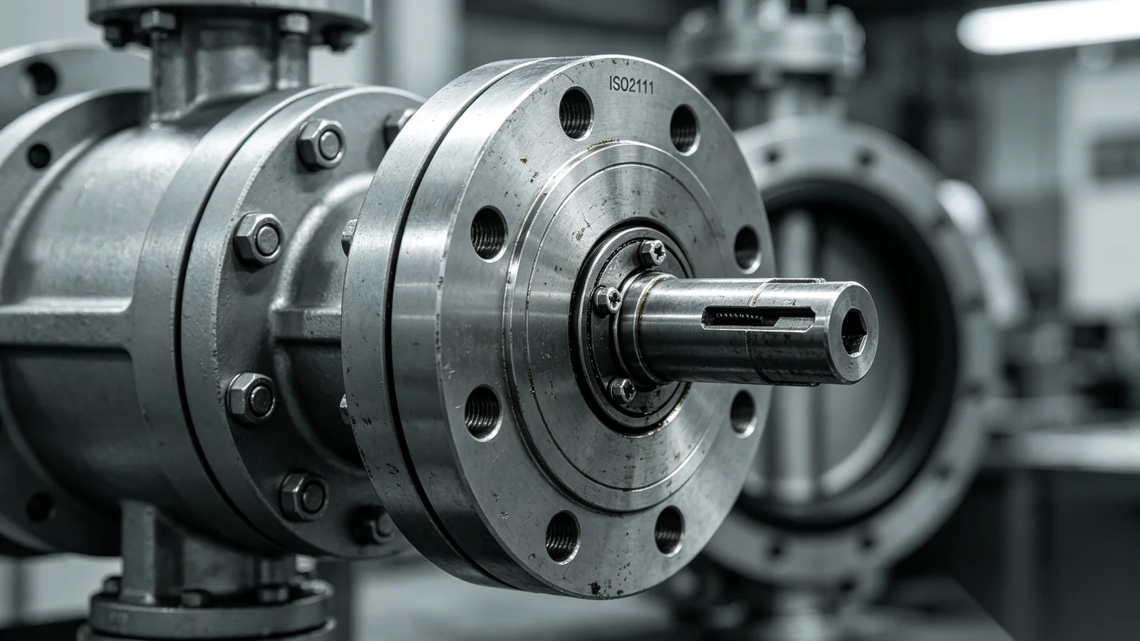
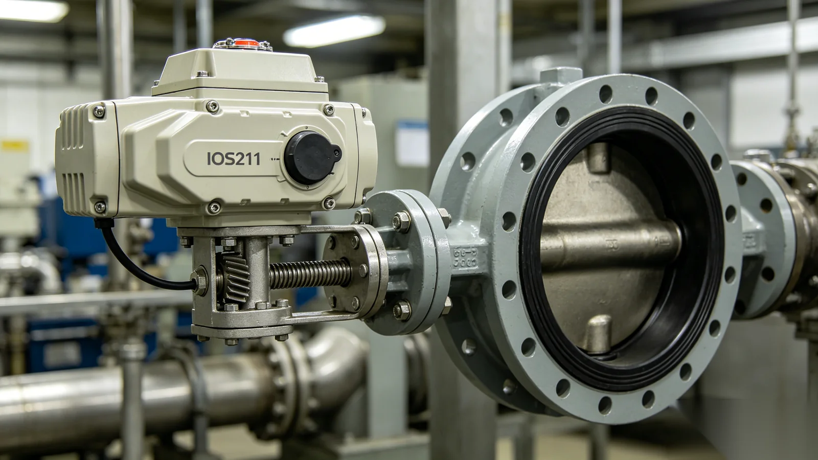
ISO 9001 API 6D CE / PED EN

Support · Engineering Standards

ISO5211 Standards for Valve Gear Operators and Actuator Mounting — Complete Guide

ISO5211 is the internationally recognized standard that defines the mounting interface between industrial valves, manual gear operators, and automated actuators. Published by the International Organization for Standardization, it establishes flange dimensions, bolt circle geometry, drive shaft connections, and mounting requirements that enable mechanical compatibility and interchangeability across manufacturers. For engineers specifying worm gear operators, electric actuators, or pneumatic drives on butterfly, ball, plug, and gate valves, understanding ISO5211 is essential to correct procurement, simplified installation, and long-term maintainability. This guide explains what the standard covers, how F-series flange sizes are selected, and how to verify compatibility before equipment reaches site.

F-Series Flange Dimensions Actuator Mounting Interface Gearbox Compatibility

Standard Overview

What Is ISO5211?

ISO5211 — formally ISO 5211 — is the international standard for the mounting of part-turn actuators and gear operators on industrial valves. It was developed to replace a patchwork of national and manufacturer-specific flange patterns with a single, dimensionally controlled interface that valve makers, gearbox suppliers, and actuator manufacturers could all reference. The standard specifies the geometric relationship between the valve top flange and the equipment mounted above it, ensuring that bolt holes, center bores, and drive connections align without custom adapter plates in the majority of applications. For procurement teams and design engineers, ISO5211 provides a common language: when a valve datasheet states F07 and an actuator catalog lists F07, the mounting interface is defined by the same dimensional tables regardless of brand origin.

  • Mounting Flange DimensionsDefines the outer flange diameter, thickness, and face geometry for each F-series size — the physical platform on which gear operators and actuators bolt to the valve.
  • Bolt Circle DimensionsSpecifies the diameter of the bolt circle and the number, size, and angular position of mounting holes for each flange class.
  • Drive Shaft InterfacesStandardizes stem coupling geometry including square drives, double-square profiles, keyed shafts, and stem bore dimensions for torque transmission.
  • Actuator Mounting RequirementsEstablishes the dimensional envelope and connection rules that electric, pneumatic, and hydraulic actuators must follow to mount on ISO5211-compliant valve tops.
  • Gearbox Mounting CompatibilityEnables worm gear operators, bevel gearboxes, and multi-turn gear units to share the same valve mounting interface as direct-mounted actuators.

Engineering Value

Why ISO5211 Matters

Before ISO5211 achieved widespread adoption, valve automation projects frequently required custom mounting brackets, non-standard adapter plates, and manufacturer-specific stem couplings. Each valve-actuator combination demanded individual engineering review, extended lead times, and field modifications when substitute equipment was needed. ISO5211 eliminated much of this friction by creating a standardized mounting interface that multiple suppliers could design to independently — yet still connect together on site. For EPC contractors managing multi-vendor valve packages, OEM valve manufacturers building actuator-ready products, and plant engineers planning future upgrades, the standard delivers measurable project and lifecycle benefits.

Interchangeability

Products from different manufacturers connect using the same ISO5211 flange designation and drive interface. A gear operator from one supplier can be replaced with a unit from another without redesigning the valve top or fabricating custom adapters — provided flange size, drive geometry, and torque ratings are matched.

Simplified Installation

Standardized bolt patterns and stem coupling dimensions reduce installation complexity in the field. Technicians reference a single set of flange tables rather than interpreting proprietary drawings for every valve-actuator combination on a project.

Reduced Engineering Costs

Design teams specify equipment using F-series codes rather than drafting custom mounting interfaces for each valve size. This accelerates tender preparation, reduces drawing revisions, and lowers the engineering hours required per valve automation package.

Faster Maintenance

When a gear operator or actuator fails in service, ISO5211-compliant replacements can be sourced from multiple vendors and installed without valve modification. Maintenance teams stock fewer adapter variants and complete turnaround work faster.

Improved Project Standardization

Facilities and EPC projects apply consistent ISO5211 specifications across valve types, sizes, and process areas. This simplifies spare parts management, training, and future automation upgrades throughout the plant lifecycle.

Interface Anatomy

ISO5211 Mounting Components

The ISO5211 mounting interface is more than a bolt pattern — it is a coordinated system of flange geometry, drive connection, and alignment features that together transmit valve operating torque safely and reliably. Understanding each component helps engineers verify compatibility between valves, gear operators, and actuators before procurement, and helps field technicians diagnose mounting failures when bolt patterns appear to match but the assembly does not perform correctly. The four sub-components below form the core of every ISO5211 connection.

Mounting Flange

The mounting flange provides the structural connection between the valve body and the gear operator or actuator. ISO5211 defines flange outer diameter, thickness, face flatness requirements, and the F-series designation that identifies each size class.

Drive Shaft Interface

Torque passes from the operator to the valve stem through standardized drive connections — square drives, double-square profiles, and keyed shafts are the most common. Stem bore diameter and engagement depth must match for full torque transmission without slippage.

Fastener Locations

Bolt circle diameter, hole count, hole diameter, and angular spacing are fixed for each F-series size. Correct fastener grade and torque sequence are essential to maintain flange contact pressure and prevent misalignment under operating loads.

Centering Features

Dowel pins, center bores, and register diameters maintain concentric alignment between the valve stem and the operator drive. Proper centering prevents side loading, uneven wear, and premature seal failure in the stem packing area.

ISO5211 mounting flange components showing bolt pattern and drive shaft interface
F-Series Mounting flange interface

Size Selection

Common ISO5211 Flange Sizes

ISO5211 defines multiple flange sizes identified by F-series designations — from compact F03 interfaces for small butterfly valves to large F30 patterns for high-torque pipeline and hydropower applications. Flange size selection depends primarily on required output torque, valve stem diameter, and the physical envelope of the gear operator or actuator. The table below summarizes the most commonly specified sizes in industrial valve automation projects.

Flange Size Typical Applications
F03Compact butterfly valves, small pneumatic actuators, light-duty isolation in HVAC and utility systems
F04Small ball valves, compact gear operators, laboratory and pilot plant automation
F05Medium butterfly valves, compact electric actuators, water distribution and building services
F07Medium butterfly and ball valves, worm gear operators, general industrial process isolation
F10Large butterfly valves, industrial process valves, water treatment isolation and throttling duty
F12Water treatment plants, power generation auxiliary systems, large ball valve automation
F14Large diameter ball valves, high-torque industrial isolation, pipeline block valves
F16Major pipeline isolation, large industrial process valves, heavy-duty gear operator mounting
F25Large diameter valves, hydropower penstock isolation, high-torque multi-turn applications
F30Very large valves, hydropower and pipeline systems requiring maximum torque transmission capacity

Flange Designations

Understanding ISO5211 Naming Conventions

The "F" designation in ISO5211 refers to flange size — each number corresponds to a defined set of dimensional values including flange diameter, bolt circle, hole count, and maximum recommended torque. Understanding these designations allows engineers to communicate mounting requirements precisely across valve, gearbox, and actuator suppliers without ambiguity. F05 represents one of the most compact industrial interfaces, commonly used on small butterfly valves and compact electric or pneumatic actuators where space is limited and operating torque is moderate. F07 is among the most frequently specified sizes in general industry — it serves medium butterfly valves, ball valves, and worm gear operators in water treatment, chemical processing, and general manufacturing applications where torque requirements fall in the mid-range. F10 and F12 cover larger industrial process valves, water treatment plant isolation, and power generation auxiliary systems where higher output torque and larger stem diameters require a proportionally larger mounting interface. F14 and above address large-diameter valves, high-torque pipeline isolation, hydropower penstock applications, and multi-turn gate valve automation where the mounting flange must accommodate substantial mechanical loads. When reviewing datasheets, always confirm that valve, gear operator, and actuator all reference the same F-series designation — and verify that drive shaft geometry matches within that flange class.

Manual Operation

ISO5211 and Valve Gear Operators

Worm gear operators and bevel gearboxes manufactured according to ISO5211 provide a standardized mounting interface that simplifies valve integration across project types and supplier bases. When a gear operator carries an F07 ISO5211 bottom flange, it bolts directly to any F07-compliant valve top without custom adapter fabrication — reducing engineering time and field installation risk. ISO5211-compliant gear operators also maintain actuator compatibility: the same valve can accept a manual worm gear today and be upgraded to an electric or pneumatic actuator later by swapping the mounted equipment while retaining the valve's standardized top flange. This future-proofs automation investments and reduces lifecycle cost when plants transition from manual to automated operation. Additional benefits include reduced installation time because bolt patterns and stem couplings are pre-defined, standardized engineering documentation that EPC teams can reference across multiple valve packages, and simplified spare parts procurement because flange designations are universal rather than proprietary. For OEM valve manufacturers, offering ISO5211-compliant top flanges on actuator-ready valve designs expands the addressable market for both manual and automated configurations.

Automation Integration

ISO5211 and Electric Actuators

Electric actuators for quarter-turn valves rely on ISO5211 mounting interfaces to achieve direct bolt-on installation without intermediate adapter plates in most applications. When the actuator flange, drive stem, and torque output match the valve and project requirements, commissioning time drops significantly compared to custom-mounted solutions. ISO5211 standardization delivers faster installation because field teams follow known bolt patterns, improved compatibility across actuator brands for competitive procurement, easier maintenance when actuator replacement is required during service life, and simplified replacement during upgrades when plants move from one actuator generation or supplier to another.

Actuator Selection Considerations

ISO5211 Flange Size

Confirm the actuator bottom flange matches the valve top flange designation — F07 to F07, not F07 to F10 with an undeclared adapter plate.

Output Torque

Actuator rated torque must exceed valve break and run torque with project safety factors applied — typically 1.25 to 1.5 on break torque.

Drive Shaft Dimensions

Verify square drive size, stem bore diameter, and engagement depth match the valve stem interface defined for the F-series class.

Control Requirements

Match actuator control protocol — on/off, modulating, fieldbus — to the plant DCS or SCADA architecture before confirming mechanical mounting.

Environmental Protection Ratings

Select IP67, IP68, or higher ingress protection and appropriate coatings for outdoor, underground, offshore, or submersible installation environments.

Electric actuator mounted on ISO5211 flange interface for valve automation
Actuator Ready ISO5211 direct mount

Process Automation

ISO5211 and Pneumatic Actuators

Pneumatic actuators represent one of the most common automated drive types mounted on ISO5211 valve interfaces, particularly in oil and gas production, chemical processing plants, water treatment facilities, and general industrial automation systems where compressed air infrastructure is available. Like electric actuators, pneumatic scotch-yoke and rack-and-pinion units are manufactured with standardized ISO5211 bottom flanges that bolt directly to compliant valve tops. The same compatibility rules apply: matching F-series designation, verified drive shaft geometry, and adequate torque output for safe valve operation. Pneumatic actuators offer fast cycle times and inherent fail-safe options — spring-return configurations for emergency shutdown — that make them preferred in safety-critical process applications. When specifying pneumatic actuators on ISO5211 mounts, confirm air supply pressure range, fail position requirement, and solenoid valve interface in addition to mechanical flange compatibility.

Compatibility Checklist

How to Verify ISO5211 Compatibility

Matching flange designations on datasheets is necessary but not always sufficient for full mechanical compatibility. Before placing orders or commencing installation, engineers should verify five critical interface parameters against manufacturer dimensional drawings. Our application engineering team performs this review routinely for EPC submittals and OEM programs — the checklist below captures the same verification steps used in our factory compatibility assessments.

Flange Size

Confirm matching F-series designations on the valve top flange, gear operator bottom flange, and actuator mounting interface. Cross-reference dimensional tables — do not assume compatibility from designation alone if suppliers use non-standard interpretations.

Drive Dimensions

Verify stem coupling geometry — square drive size, double-square profile, keyway width and depth, and stem bore diameter. Confirm engagement depth provides full torque transmission without bottoming or insufficient contact.

Bolt Patterns

Confirm bolt circle diameter, hole count, hole diameter, and angular position match between valve and operator. Verify fastener grade and length requirements specified by the gear operator or actuator manufacturer.

Torque Requirements

Ensure the gear operator or actuator rated output torque meets or exceeds valve break and run torque with appropriate safety factors. Undersized equipment leads to excessive effort, wear, and potential stem damage.

Environmental Requirements

Confirm IP67, IP68, or specified ingress protection ratings and corrosion-resistant coatings match the installation environment — outdoor exposure, underground chambers, marine salt spray, or chemical processing areas.

Field Lessons

Common ISO5211 Installation Mistakes

Even experienced installation teams encounter ISO5211 mounting errors that lead to stiff operation, premature wear, or complete drive failure. Most mistakes are preventable with pre-installation dimensional verification and adherence to manufacturer torque specifications. The four errors below appear repeatedly in field service reports and warranty claims.

Incorrect Flange Selection

Specifying or installing a gear operator or actuator with the wrong F-series flange — for example mounting an F10 unit on an F07 valve top using an improvised adapter without engineering approval. Bolt holes may partially align, creating a false sense of compatibility while leaving the drive misaligned and fasteners understressed.

Shaft Misalignment

Failing to verify concentric alignment between the valve stem and operator drive before final bolt tightening. Side loading on the stem and drive coupling accelerates packing wear, increases operating torque, and can cause square drive slippage under break torque conditions.

Incorrect Fasteners

Using wrong bolt grade, insufficient length, or improper torque sequence when mounting the gear operator to the valve flange. Under-torqued fasteners allow flange separation under load; over-torqued fasteners can distort mounting faces and compromise stem alignment.

Ignoring Torque Requirements

Installing a gear operator or actuator without verifying that rated output torque meets valve break and run requirements with safety factor. The mounting interface may fit mechanically while the drive is undersized for the application — leading to operator injury risk, gear wear, and valve stem damage.

Industry Coverage

ISO5211 Applications Across Industries

ISO5211 mounting interfaces are specified across virtually every industrial sector where quarter-turn and multi-turn valves require manual gear operators or automated actuators. The standard's universal adoption means engineers in diverse industries reference the same F-series tables and compatibility rules.

Water Treatment

Municipal and industrial water plants use ISO5211 mounts on butterfly and gate valve gear operators for isolation, throttling, and backwash duty.

Oil & Gas

Pipeline block valves, wellhead isolation, and refinery process valves rely on ISO5211 interfaces for pneumatic and electric actuator mounting.

Power Generation

Thermal and nuclear plants specify ISO5211 gear operators on auxiliary system isolation valves and cooling water circuit controls.

Mining

Slurry isolation, tailings management, and process water valves use ISO5211-mounted worm gear operators in abrasive duty environments.

Marine and Offshore

Ballast, cargo, and process isolation valves on vessels and platforms use ISO5211 flanges with corrosion-resistant gear operators and actuators.

Chemical Processing

Reactor isolation, transfer line block valves, and emergency shutdown valves mount actuators on ISO5211 interfaces for rapid automation response.

Industrial Automation

Manufacturing plants standardize on ISO5211 for consistent valve automation across production lines, utilities, and safety systems.

Hydropower Systems

Penstock isolation, spillway control, and turbine bypass valves use large F-series ISO5211 mounts for high-torque gear operator applications.

Lifecycle Value

Benefits of ISO5211-compliant Gear Operators

Specifying ISO5211-compliant worm gear operators delivers advantages that extend from initial project engineering through decades of plant operation. The standardized interface reduces cost, risk, and downtime at every stage of the asset lifecycle.

Global compatibility

Gear operators from international suppliers mount on the same valve top flanges without custom engineering.

Simplified engineering

F-series designations replace proprietary mounting drawings in specifications and tender documents.

Reduced installation costs

Standard bolt patterns and drive couplings eliminate adapter plate fabrication and field modification.

Easier actuator upgrades

Plants transition from manual to automated operation by swapping mounted equipment on the same valve flange.

Faster maintenance

Replacement gearboxes and actuators install without valve modification when flange and drive geometry match.

Lower lifecycle costs

Competitive sourcing, reduced spare parts inventory, and shorter outage duration reduce total cost of ownership.

Improved procurement flexibility

Multiple approved suppliers can bid on the same F-series specification without technical exceptions.

FAQ

Frequently Asked Questions

What does ISO5211 define?+

ISO5211 defines the dimensional requirements for mounting part-turn actuators and gear operators on industrial valves. This includes mounting flange dimensions and F-series size designations, bolt circle diameter and hole patterns, drive shaft interface geometry such as square drives and keyed connections, and the mechanical relationship between the valve top flange and the equipment mounted above it. It does not define valve body dimensions, pressure ratings, or actuator control protocols — only the standardized mounting interface that enables mechanical connection and torque transmission between valve, gear operator, and actuator.

Does ISO5211 guarantee full compatibility?+

ISO5211 guarantees dimensional compatibility of the mounting interface when all parties manufacture to the standard — but engineers must still verify flange size, drive shaft geometry, torque rating, and environmental protection independently. Two products both labeled F07 may differ in stem bore depth, square drive size within the F07 class, or maximum rated torque. Always cross-reference manufacturer dimensional drawings and confirm drive coupling engagement before assuming full compatibility. Adapter plates may still be required when transitioning between closely related but non-identical interface variants.

Can an actuator be upgraded later if ISO5211 is used?+

Yes — one of the primary benefits of ISO5211 is future upgrade flexibility. A valve fitted with a manual worm gear operator on an ISO5211 F07 flange can later accept an F07 electric or pneumatic actuator by removing the gear operator and bolting the actuator to the same valve top, provided drive shaft geometry and torque requirements are satisfied. This allows plants to defer automation capital expenditure while preserving the option to automate without valve modification. Declutchable gear operators offer an intermediate path — manual operation with actuator-ready mounting for later integration.

What is the most common ISO5211 flange size?+

F07 is the most commonly specified ISO5211 flange size in general industrial applications. It serves medium butterfly valves, ball valves, and worm gear operators across water treatment, chemical processing, HVAC, and general manufacturing. F05 is widely used for smaller butterfly valves and compact actuators, while F10 and F12 appear frequently in larger water treatment and power generation projects. The correct size depends on valve torque requirements and stem diameter — not on industry alone — so always size from calculated break and run torque rather than assuming F07 for all applications.

Are worm gear operators available with ISO5211 interfaces?+

Yes. Worm gear operators, bevel gearboxes, and multi-turn gear units are routinely manufactured with ISO5211 bottom mounting flanges across the full F-series range from F03 to F30 and above. ISO5211-compliant worm gear operators bolt directly to actuator-ready valve tops and accept actuator mounting on their output flanges when configured for automation. ValveWormGear manufactures quarter-turn and multi-turn gear operators with ISO5211 interfaces for water treatment, oil and gas, power generation, mining, and general industrial applications — with engineering support for flange verification, torque sizing, and actuator compatibility review.

Need Help Selecting an ISO5211 Gear Operator?

Our application engineering team provides assistance with ISO5211 mounting interface selection, actuator matching, flange compatibility verification, and valve automation system configuration. Whether you are sizing a single worm gear operator for a water treatment isolation valve or specifying actuator-ready gearboxes for an EPC valve package, we deliver documented engineering recommendations aligned to ISO5211 standards and your project torque requirements. Contact us for flange verification, CAD models, and compatibility review before your next procurement cycle.