ISO 9001 API 6D CE / PED EN

Support · Installation Guidance

Complete Installation Guide for Worm Gear Operators and Valve Gearboxes

Proper installation is essential for reliable valve performance, personnel safety, and long service life. Whether you are mounting a quarter-turn worm gear operator on a butterfly valve in a water treatment plant, integrating a bevel gearbox on a penstock gate at a hydropower facility, or commissioning multi-turn gear units in oil and gas, mining, power generation, or industrial automation environments, correct installation prevents premature wear, operational issues, and costly unplanned downtime. This guide consolidates field-proven procedures used by EPC contractors, OEM valve manufacturers, and plant maintenance teams worldwide.

Scope: This installation guidance center covers worm gear operators, bevel gear operators, quarter-turn systems, and multi-turn valve gearboxes — from pre-installation inspection through commissioning and post-installation maintenance recommendations.

ISO 5211 Mounting Shaft Alignment Commissioning Procedures

Pre-Install

Before Installation

Before any mounting hardware is tightened or any stem coupling is engaged, verify that all components have been received, inspected, and confirmed against project specifications. Skipping pre-installation checks is one of the most common causes of field rework — damaged housings installed under schedule pressure, incorrect model numbers mounted to incompatible valves, and missing documentation discovered only at commissioning. A structured receiving inspection takes minutes and prevents days of corrective work.

Check Product Identification

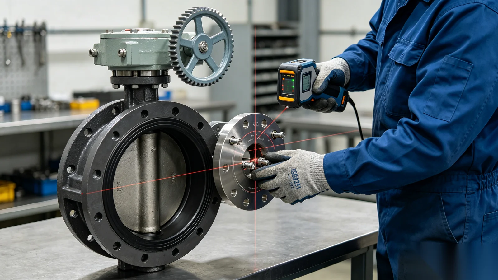
Verify the model number, gear ratio, torque rating, valve compatibility, mounting standard, and environmental protection level against your purchase order and valve datasheet. Confirm that the gear operator's rated output torque meets or exceeds the calculated valve operating requirement with appropriate safety factor. Check the ISO 5211 flange code, stem bore or coupling type, and any adapter plate part numbers included in the shipment. Specifications must match application requirements — including temperature range, duty class, and corrosion protection — before proceeding to installation.

Inspect for Shipping Damage

Inspect the housing condition, handwheel, input shaft, mounting flange, fasteners, and protective coatings for signs of impact, corrosion, or transit damage. Look for cracked castings, bent handwheel spokes, nicked shaft surfaces, stripped threads, and compromised paint or coating systems. Verify that all nameplate data is legible and matches the order. Do not install damaged equipment — contact the supplier immediately with photographic documentation and request replacement or repair authorization before mounting to the valve.

Review Technical Documentation

Ensure installers have access to product datasheets, CAD drawings, mounting dimensions, installation instructions, and torque specifications before work begins. Confirm bolt grade requirements, tightening sequences, lubrication type, and any orientation restrictions noted in the manual. For EPC projects, cross-reference submittal documents against delivered equipment. Having documentation on site during installation allows real-time verification of flange dimensions, stem engagement depth, and travel stop settings rather than discovering discrepancies after the gear operator is already bolted in place.

Site Readiness

Installation Preparation

Thorough site preparation ensures safe, efficient installation and reduces the risk of alignment errors or personnel injury. Confirm that the work area is accessible, adequately lit, and free from process hazards before bringing equipment to the valve location.

Required Tools

Gather common installation tools before starting work to avoid partial assembly and repeated trips. Typical requirements include a calibrated torque wrench, alignment tools or dial indicators, a complete socket set, hex key sets matched to fastener sizes, appropriate lifting equipment for heavier gear operators, and measuring tools for flange and stem verification.

  • Calibrated torque wrench
  • Socket and hex key sets
  • Alignment tools / dial indicator
  • Lifting slings or hoist
  • Feeler gauges and calipers
  • Thread lubricant (if specified)

Safety Precautions

Always follow site safety procedures before beginning installation work. Implement lockout/tagout on adjacent process equipment, wear appropriate personal protective equipment including gloves and safety footwear, and use safe lifting practices with rated rigging for gear operator weight. Provide fall protection where work is performed at elevation. When electric actuators or control wiring are present, ensure electrical isolation and verify zero-energy state before mechanical work. Never stand under suspended loads, and maintain clear communication between rigging and installation personnel throughout the mounting process.

Verify Valve Position

Confirm valve open position, valve closed position, and gearbox operating position before mounting the gear operator. Ensure travel stops on both the valve and gearbox are properly aligned with the intended stroke. Incorrect positioning at installation causes limited valve travel, incomplete shutoff, or over-travel damage discovered only during commissioning. Mark reference positions on the stem or coupling if helpful for post-installation verification. For quarter-turn valves, verify disc orientation relative to piping and that the gearbox handwheel direction matches site operating conventions.

ISO 5211 Mounting

Mounting the Gear Operator

Mounting is the most critical phase of installation — concentric alignment and proper fastener torque directly determine gearbox service life and valve operating reliability. Follow the procedures below in sequence and do not energize or place the valve into service until all mounting checks are complete.

Verify ISO5211 Compatibility

Check flange size, shaft dimensions, bolt circle dimensions, and drive interface compatibility before lifting the gear operator into position. ISO 5211 defines the dimensional relationship between valve top flanges and gear operator mounting interfaces — mismatched F-series codes, incorrect stem bore diameters, or incompatible drive square sizes cause misalignment and excessive stress on worm sets and valve stems. Verify adapter plate requirements when connecting non-standard valve flanges to catalog gear operators.

Shaft Alignment

Correct alignment is critical for long-term reliability. Verify concentric alignment between the valve stem and gear operator input, proper engagement depth of stem nuts or couplings, smooth rotation through the full stroke without binding, and absence of side loading on the stem. Use alignment tools where available and rotate the assembly by hand before final bolt tightening. Misalignment significantly reduces gearbox life, increases operating torque, and can cause premature seal failure or stem damage within the first months of service.

Secure Mounting Hardware

Use appropriate fasteners and tightening procedures specified in the installation manual. Follow published torque specifications for mounting bolts, tighten in a cross pattern to ensure even seating of the flange interface, and verify that the gear operator sits flat against the valve top flange without gaps or rocking. Recheck fastener torque after initial commissioning cycles — thermal expansion and vibration can cause relaxation in the first weeks of operation. Document torque values in the installation record for future maintenance reference.

Engineer aligning worm gear operator with ISO5211 flange on valve
Mount & Align ISO 5211 interface verification

90° Rotation

Installing Quarter-turn Gear Operators

Quarter-turn gear operators convert handwheel rotation into 90-degree valve movement for isolation and modulating service on butterfly, ball, and plug valves. Installation requirements differ from multi-turn systems — orientation, travel stops, and handwheel accessibility demand particular attention.

Butterfly Valve Applications

Quarter-turn gear operators are commonly installed on butterfly valves, ball valves, and plug valves across water treatment, HVAC, and industrial process applications. Verify valve orientation relative to piping flow direction, gearbox orientation so the handwheel is accessible from the designated operating platform, and that indicator positions match open/closed labeling on the P&ID. Confirm adequate clearance for future actuator mounting if automation is planned. Check that the disc does not contact piping internals at any point through the full 90-degree stroke before setting travel stops.

Travel Stop Adjustment

After installation, confirm full open and full closed positions by operating the valve through its complete stroke. Adjust internal travel stops if required to prevent over-travel beyond the valve manufacturer's recommended limits. Proper stop adjustment protects both the valve seat and the gearbox worm set from mechanical overload at end positions. Record final stop settings and verify that the position indicator accurately reflects valve state. Re-check stops after the first several operating cycles under process conditions, as seating torque can shift effective end positions slightly on soft-seated valves.

Linear Stem Drive

Installing Multi-turn Gear Operators

Multi-turn gear operators drive linear stem movement for gate valves, globe valves, sluice gates, and water control structures. Installation focus shifts from angular travel limits to stem alignment, straight-line movement, and consistent torque through extended stroke lengths.

Gate Valve Applications

Multi-turn systems are used for gate valves, globe valves, sluice gates, and water control systems where linear stem travel requires high reduction ratios. Verify stem thread engagement, bonnet clearance, and that the gear operator mounting height allows full stroke without mechanical interference. For rising stem designs, confirm adequate headroom for stem extension at full open position.

Stem Alignment Verification

Verify straight stem movement throughout the full valve travel with no binding, side loading, or eccentric rotation. The stem must move smoothly without galling or uneven resistance that indicates misalignment between the gearbox output and valve stem nut. Check stem guide clearances and packing load — excessive packing compression mimics gearbox problems but originates from valve-side conditions. Use slow manual operation to feel for tight spots before applying full operating force.

Gearbox Travel Testing

Operate the valve through multiple complete cycles during installation testing. Confirm consistent operating torque from open to closed, smooth handwheel rotation without catching or noise, proper valve response at each position, and no abnormal sounds from the worm set or stem interface. Compare operating effort against baseline expectations from the torque selection calculation. Document any variation for engineering review before placing the valve into process service.

Automation

Actuator Integration

Many installations combine manual gear operators with electric or pneumatic actuators for normal operation and manual override capability. Plan actuator integration during initial installation to avoid costly field modifications to mounting interfaces, clearances, or control wiring routes.

Electric Actuator Installation

Verify ISO5211 interface compatibility between the gear operator and electric actuator mounting flange, confirm that actuator output torque meets valve requirements without overloading the worm gear train, and check voltage specifications and control system requirements against site electrical standards. Review limit switch configuration, torque seating settings, and motor duty class for the application. Ensure adequate clearance for actuator maintenance and cable entry points.

Pneumatic Actuator Installation

Check mounting interfaces, air supply requirements, operating pressure range, and control signal compatibility with the plant instrument air system. Verify scotch-yoke or rack-and-pinion actuator orientation relative to the gear operator and valve. Confirm that pneumatic piping routes do not obstruct handwheel access or manual override operation.

Manual Override Systems

Confirm emergency manual operation capability, declutching mechanism operation, handwheel accessibility from the designated platform, and safe switching procedures between powered and manual modes. Train operators on override engagement before commissioning. Verify that override operation does not require special tools unavailable during an emergency shutdown.

Pre-Service Verification

Commissioning Procedures

Commissioning validates that installation quality meets engineering requirements before the valve is placed into process service. Follow structured functional and operational testing to confirm reliable performance and document baseline conditions for future maintenance comparison.

Engineer performing commissioning and operational testing on valve gear operator
Commission Functional & operational testing

Initial Functional Testing

Before placing the system into service, verify valve movement through the full design stroke, gearbox operation smoothness and handwheel direction, travel limit settings at both end positions, fastener security on all mounting interfaces, and alignment condition under operating load. Check position indication accuracy and any limit switch or feedback device operation. Confirm lubrication levels where applicable and that housing breather or drain plugs are correctly installed for the mounting orientation.

Operational Testing

Cycle the valve multiple times under conditions as close to design as safely achievable before process introduction. Observe smooth operation without binding, consistent torque effort through the stroke, proper seating at the closed position, absence of abnormal vibration, and no unusual sounds from the gearbox or stem interface. Record operating torque at reference positions for comparison during future maintenance inspections. For automated installations, verify actuator torque limiting, end-position confirmation, and control system feedback.

Leak Inspection

Inspect surrounding systems for process leakage at the valve body, seal interfaces, and stem packing. Check mounting interface areas for signs of external leakage paths. Verify environmental sealing integrity of the gear operator housing — particularly shaft seals and cover gaskets — before exposure to weather or washdown conditions in outdoor installations.

Avoid These Errors

Common Installation Mistakes

Field experience shows that most gear operator failures within the first year of service trace to installation errors rather than manufacturing defects. Review these common mistakes before commissioning and during installer training programs.

Incorrect Gearbox Sizing

Undersized gear operators require excessive operating force, accelerate worm and wheel wear, and reduce service life well below the rated cycle count. Oversized units add unnecessary cost and may not engage stems correctly. Always size against break-to-open torque with appropriate safety factor rather than estimated values.

Improper Shaft Engagement

Insufficient stem nut engagement depth or incorrect coupling alignment causes gear damage, persistent misalignment, and torque loss at the valve interface. Verify engagement depth against installation drawing specifications and rotate manually to confirm positive drive before final bolt-up.

Over-tightening Fasteners

Exceeding specified mounting bolt torque distorts flanges, introduces misalignment, and creates mechanical stress concentrations that crack cast housings over time. Use calibrated torque wrenches and follow cross-pattern tightening sequences — never use impact tools on gear operator mounting hardware.

Incorrect Travel Stop Settings

Travel stops set beyond the valve's mechanical limits cause valve damage, reduced sealing performance, and gearbox overload at end positions. Always set stops based on actual valve stroke verification rather than default factory positions, which may not match your specific valve configuration.

Site Conditions

Environmental Installation Considerations

Installation environment affects gear operator selection, mounting orientation, sealing requirements, and maintenance access planning. Address environmental factors during installation — not after premature corrosion or water ingress appears in service.

Outdoor Installations

Outdoor gear operators face UV exposure, rain, temperature variation, and corrosion from atmospheric pollutants. Verify that the specified protection class matches site conditions, orient housing breathers and drains correctly for the mounting position, and consider sun shields or weather covers for extreme climates. Apply supplementary corrosion protection to mounting fasteners if not supplied in stainless steel.

Underground Chambers

Installations in valve pits and underground chambers require adequate drainage to prevent standing water contact with the gear operator, moisture protection through appropriate IP ratings, and accessibility for future maintenance without confined-space complications. Verify lifting points and headroom for gear operator removal during overhaul.

Marine and Offshore Environments

Marine and offshore installations demand enhanced corrosion protection, stainless steel components for external hardware, enhanced sealing systems on all shaft penetrations, and regular inspection intervals due to aggressive salt spray exposure. Document coating condition at installation as a baseline for future corrosion monitoring programs.

After Commissioning

Post-installation Maintenance Recommendations

Installation quality establishes the baseline for long-term reliability — but sustained performance requires structured follow-up inspection and record keeping from the first day of operation.

First Inspection

Schedule an inspection after initial operation — typically within the first 30 to 90 days depending on duty cycle. Check fastener condition and re-torque mounting bolts if specified, verify alignment has not shifted under thermal or process loading, measure operating torque against commissioning baseline, and inspect sealing condition at housing joints and shaft penetrations.

Preventive Maintenance Schedule

Establish regular maintenance intervals based on operating frequency, environmental conditions, valve type, and application criticality. High-cycle modulating service requires more frequent lubrication and wear inspection than occasional isolation duty. Integrate gear operator maintenance into the plant CMMS with tasks linked to the specific valve tag number and gear operator serial.

Record Keeping

Maintain records for installation date, installer identity, commissioning test results, inspection history, maintenance activities, and any replacement components. Complete records support warranty claims, root cause analysis after failures, and informed decisions during plant turnarounds. Store torque test certificates and material reports with the equipment file for the asset lifecycle.

Common Questions

Frequently Asked Questions

How do I know if the gearbox is aligned correctly?+

Correct alignment is confirmed through several practical checks during installation. The valve stem and gear operator input should share a common axis — verify concentricity with a dial indicator or alignment tool where precision is required. Rotate the assembly by hand through the full stroke: movement should be smooth and uniform without tight spots, eccentric wobble, or increasing resistance at specific angles. The gear operator should sit flat against the valve flange with all mounting bolts engaging evenly — no gaps or rocking at the interface. Listen for abnormal contact sounds during slow rotation. After bolt-up, operating torque should remain consistent with pre-installation manual rotation. If operating effort increases significantly after mounting, misalignment is likely and the assembly should be loosened, realigned, and re-torqued before commissioning. For critical applications, document alignment verification in the installation record and request engineering review if any check fails.

Should travel stops be adjusted after installation?+

Yes — travel stops should always be verified and typically adjusted after installation, because factory default settings rarely match the exact stroke of your specific valve and mounting configuration. After mounting the gear operator, operate the valve manually to the physical open and closed limits defined by the valve manufacturer. Adjust internal stops so the gearbox prevents over-travel without restricting the valve from reaching its fully seated or fully open design position. For quarter-turn valves, confirm exactly 90 degrees of movement. For multi-turn systems, set stops at the point where the gate or disc reaches full travel without mechanical interference. Mark and record final stop positions. Re-check after the first several process cycles, as seating torque on soft-seated valves can shift effective end positions slightly. Never rely on factory stop settings alone — incorrect stops are a leading cause of valve seat damage and gearbox overload within the first weeks of service.

Can gear operators be installed outdoors?+

Yes, gear operators are routinely installed outdoors in water treatment plants, pipeline stations, mining sites, and offshore facilities — provided the specified environmental protection class matches site conditions. Verify the IP rating against expected rain exposure, washdown requirements, and temporary submersion risk. Outdoor installations require correct orientation of housing breathers and drain plugs, intact shaft seals, and protective coatings suitable for UV and atmospheric corrosion. In coastal or industrial pollution environments, specify enhanced corrosion protection or stainless steel external hardware. Consider weather covers or sun shields in extreme climates to reduce thermal cycling stress on seals and lubricant. Document coating condition at installation and include the gear operator in regular outdoor inspection rounds. If your site conditions exceed standard catalog protection, contact our engineering team for upgraded sealing and material options before installation rather than discovering water ingress after the first rainy season.

How often should mounting bolts be checked?+

Mounting bolts should be torque-checked at installation, again after the first week of operation, and at the first scheduled maintenance interval — typically 30 to 90 days depending on duty cycle and vibration environment. Thermal cycling, process vibration, and initial gasket compression can cause bolt relaxation during early service. After the initial period, include mounting bolt inspection in the regular preventive maintenance schedule — annually for standard isolation service, or more frequently for high-vibration or high-temperature applications. Use the same calibrated torque wrench and cross-pattern tightening procedure specified in the installation manual. Record torque values in the maintenance log and investigate any bolt that requires repeated re-torquing, as this may indicate flange distortion, misalignment, or incorrect bolt grade. Never allow mounting hardware to remain loose — bolt failure or gear operator movement on the valve flange causes immediate misalignment and can damage both the gearbox and valve stem within a single operating cycle.

Can electric actuators be added after installation?+

Electric actuators can often be added after initial manual gear operator installation, but compatibility must be verified before procurement to avoid costly field modifications. Confirm that the existing gear operator provides a suitable ISO 5211 interface, adequate clearance for the actuator envelope, and compatible drive coupling or declutching mechanism. The combined actuator and gearbox assembly must meet valve torque requirements without overloading worm sets. Review electrical supply availability, control signal wiring routes, and maintenance access with the actuator installed. In many cases, selecting a gear operator with integrated actuator mounting provisions during initial installation is more cost-effective than retrofitting later. If you plan to automate in a future project phase, note this during initial installation so orientation, clearances, and conduit routes can be planned accordingly. Contact our engineering team with your existing gear operator model and valve datasheet for a retrofit compatibility assessment before ordering an actuator.

Need Installation Assistance?

Our engineering team provides hands-on support for gearbox installation, actuator integration, mounting compatibility verification, and commissioning procedures tailored to your project conditions. Whether you are installing a single quarter-turn operator on a plant upgrade or managing gear operator deployment across a multi-site EPC program, we deliver project-specific recommendations backed by ISO 5211 application experience and field-validated procedures. Submit your valve datasheet, mounting photos, and operating environment details — and receive engineering guidance you can document from first bolt-up through reliable long-term service.