ISO 9001 API 6D CE / PED EN

Support · Operation Guidance

Operating Instructions for Worm Gear Operators and Valve Gearboxes

Proper operation ensures safe valve control, reliable performance, and long service life across demanding industrial environments. Whether you are manually operating a worm gear operator on an isolation valve in a water treatment plant, controlling process flow through a quarter-turn gearbox in oil and gas service, or managing multi-turn gear units at a power generation facility, following established operating procedures protects personnel, equipment, and process integrity. This operation manual hub consolidates field-proven guidance for operators, maintenance technicians, and control room personnel responsible for valve gearbox systems worldwide.

Scope: This web-based operation manual covers worm gear operators, bevel gear operators, quarter-turn gearboxes, and multi-turn valve operating systems — including manual handwheel operation, torque considerations, electric actuator integration, position indication, and emergency override procedures for mining, marine, power plant, and industrial automation applications.

Manual Handwheel Operation Torque & Position Control Actuator Override Procedures

Equipment Overview

Product Overview

Valve gear operators are mechanical transmission devices that transfer torque from a handwheel, electric actuator, or other drive source to an industrial valve stem or shaft. By multiplying input torque through precision worm and wheel sets or bevel gear trains, these units enable operators to move large valves that would otherwise require impractical manual effort. Understanding what a gear operator does — and how it interfaces with your valve and automation system — is the foundation for safe, effective daily operation in any process environment.

Primary Functions

  • Torque multiplication
  • Controlled valve movement
  • Manual operation capability
  • Position control
  • Emergency operation capability
  • Automation interface support

Typical Applications

Valve gear operators and worm gear operators are installed across a wide range of valve types and process services. The application determines gearbox selection, operating torque requirements, and whether quarter-turn or multi-turn operation is required.

Butterfly valves Ball valves Plug valves Gate valves Globe valves Knife gate valves

Personnel Safety

Safety Information

All personnel should review applicable safety procedures and obtain proper authorization before operating any valve gear operator or associated actuator system. Valve operation affects process conditions, pressure containment, and personnel safety — treat every operating action as a controlled procedure, not a routine habit.

General Safety Precautions

Safe valve gearbox operation depends on disciplined adherence to plant safety regulations and equipment-specific operating limits. Operators must understand both what to do and what to avoid when moving valves under process conditions. The following guidelines apply to all manual and automated operating scenarios covered in this operation manual.

Always

  • Follow plant safety regulations and permit requirements
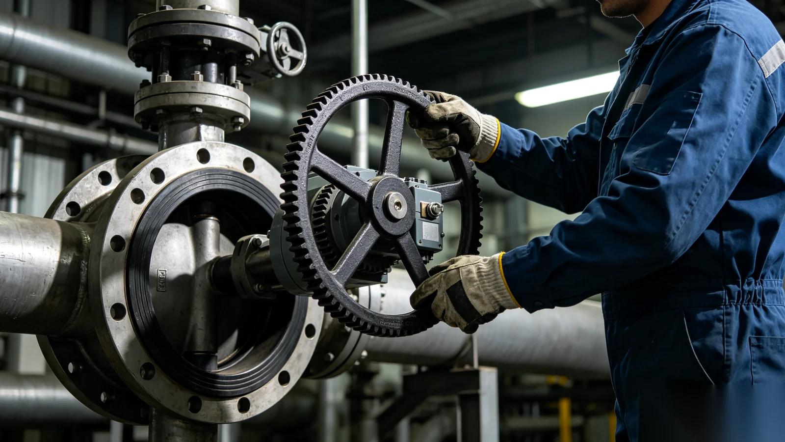
  • Wear appropriate personal protective equipment (PPE)
  • Confirm operating authority before moving critical valves
  • Verify process conditions are safe for the intended valve movement
  • Use proper operating procedures documented for your facility

Never

  • Force a seized valve with pipe wrenches or cheater bars
  • Use excessive leverage beyond the rated handwheel design
  • Modify gearbox components, stops, or drive interfaces in the field
  • Operate damaged equipment without engineering assessment

Authorized Personnel

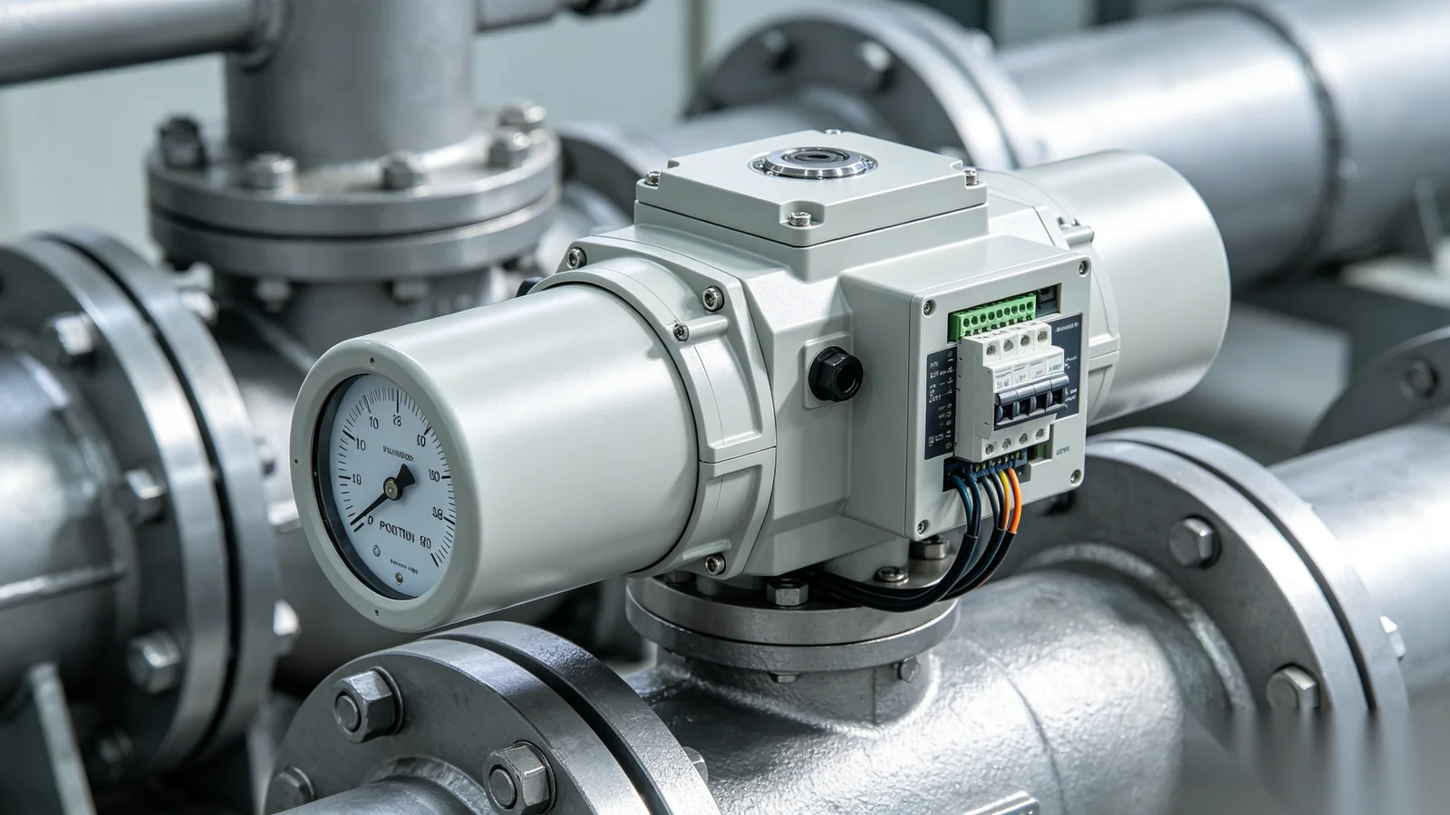
Only trained and authorized personnel should operate valve gear operators, actuator systems, emergency shutdown equipment, and critical process valves. Training should cover handwheel direction, torque limits, position indication interpretation, lockout/tagout coordination, and emergency override procedures specific to your installation. Unauthorized operation of isolation valves, blowdown valves, or safety-related equipment can create immediate process hazards. Maintain a current list of qualified operators and require refresher training when new gear operator models, actuator integrations, or operating procedures are introduced to the facility.

Mechanical Anatomy

Understanding Gear Operator Components

Familiarity with gear operator components helps operators identify problems early, perform informed inspections, and communicate effectively with maintenance and engineering teams during troubleshooting events.

Gear Housing

The gear housing encloses and protects internal transmission components from environmental exposure, contamination, and mechanical damage. It provides mounting interfaces to the valve and actuator, and maintains lubricant containment for the worm gear assembly. Inspect housing condition during routine rounds for cracks, corrosion, or seal leakage.

Handwheel

The handwheel is the primary interface for manual valve operation, providing the operator input torque that drives the gearbox mechanism. Handwheel diameter and spoke design influence the mechanical advantage available to the operator. Verify handwheel integrity and secure attachment before applying operating force.

Input Shaft

The input shaft transfers force from the handwheel or actuator drive into the gearbox mechanism. On actuator-mounted installations, the input shaft receives motor torque through a coupling or drive bushing. Shaft condition directly affects operating smoothness — nicks, corrosion, or misalignment increase required effort.

Worm Gear Assembly

The worm gear assembly is the core torque multiplication element, converting relatively low input torque at the handwheel into high output torque at the valve stem. Worm and wheel engagement provides controlled motion and inherent self-locking characteristics on many designs. Internal wear in this assembly is the primary cause of increasing operating torque over time.

Output Drive

The output drive transfers multiplied torque directly to the valve stem or shaft through a drive bushing, stem nut, or coupling interface. Proper engagement between the output drive and valve stem is essential for reliable torque transmission. Insufficient engagement depth causes slippage, while misalignment introduces side loading on the valve stem.

Position Indicator

The position indicator provides visual confirmation of valve position — open, closed, or intermediate — without requiring direct inspection of the valve internals. Indicators may be mechanical pointers, dial scales, or integrated with actuator feedback systems. Always verify indicator alignment against actual valve status before critical operating decisions.

Fundamentals

Basic Operating Principles

Valve gear operators are classified by the type of valve movement they produce. Understanding whether your installation requires quarter-turn or multi-turn operation determines handwheel revolutions, travel stop settings, and expected operating time.

Quarter-turn Gear Operators

Quarter-turn gear operators are used for butterfly valves, ball valves, and plug valves where valve travel spans 0° to 90°. The gearbox converts continuous handwheel rotation into controlled quarter-turn valve movement through a worm gear set with defined reduction ratio. A single operating sequence moves the valve from fully closed to fully open — or vice versa — within a predictable number of handwheel turns specified by the gear ratio. Operators should confirm handwheel direction conventions at their site, verify travel stops prevent over-rotation, and use smooth, steady input rather than rapid spinning that can overshoot the desired position on high-ratio units.

Multi-turn Gear Operators

Multi-turn gear operators are used for gate valves, globe valves, sluice gates, and other linear-stem designs where multiple handwheel revolutions are required to fully open or close the valve. The high reduction ratio allows operators to generate the substantial thrust needed to seat large gate valves against process pressure. Operating time is longer than quarter-turn systems — plan for the full stroke duration during startup, shutdown, and emergency procedures rather than expecting instantaneous valve movement.

Handwheel Procedures

Manual Valve Operation

Manual operation through the handwheel remains the primary operating method for many valve gear operators — whether as the normal mode of control or as backup during actuator maintenance and power outages. Follow structured procedures for opening and closing to protect valve seats, gearbox internals, and process safety.

Opening a Valve

Opening procedures establish a safe, verifiable sequence from closed to open position. Use the numbered steps below every time you move a valve toward the open position — especially on critical isolation and control valves.

  1. Confirm you have operating authorization and that process conditions permit opening
  2. Verify current valve position on the indicator and against the P&ID line-up
  3. Rotate the handwheel in the opening direction using smooth, steady force
  4. Operate continuously without impact loading or sudden reversals
  5. Continue rotation until the valve reaches the fully open position or design stop
  6. Verify the position indicator confirms full open and record the operation if required

Closing a Valve

Closing procedures require equal discipline — particularly on seated valves where final turns apply seating torque against process pressure. Never rush the closing stroke.

  1. Verify process requirements and authorization permit valve closure
  2. Rotate the handwheel in the closing direction with controlled, steady force
  3. Apply consistent torque through the stroke — avoid hammering or impact loading
  4. Approach the closed position gradually to allow proper seat engagement
  5. Stop at the designed closed position — do not exceed travel stop limits
  6. Confirm closure via position indicator and any required leak or line-up checks

Position Indication

Position indication provides three primary states relevant to daily operation. Open means the full flow path is available and the indicator aligns with the open marking on the dial or pointer scale. Closed means the valve is fully isolated and the indicator aligns with the closed marking. Intermediate positions indicate partial opening used for throttling or modulating service — verify whether your valve type is rated for intermediate operation before holding at partial stroke. Always cross-check indicator alignment, mechanical handwheel position, and actual valve status before critical operations such as line breaking, vessel entry, or emergency isolation.

Engineer rotating handwheel of heavy duty gear operator on industrial valve
Manual Operation Handwheel valve control

Force & Resistance

Operating Torque Considerations

Operating torque varies significantly based on valve size, valve type, differential pressure across the closure member, process media, temperature, and service conditions. Operators should develop a baseline sense of normal effort for each valve and investigate any deviation promptly.

Normal Torque Conditions

Under normal conditions, valve gearbox operation feels smooth and consistent from open to closed. Handwheel rotation requires predictable, uniform effort without tight spots, sudden resistance changes, or grinding sensations. Operating torque may increase slightly at the seated position on closed valves — this is expected. Document normal operating feel during commissioning for comparison during future inspections.

Abnormal Torque Conditions

Excessive operating force may indicate valve seizure, debris buildup on the closure member, mechanical damage to the gearbox or stem, improper lubrication, or incorrect gear operator sizing for actual process conditions. If abnormal torque is observed, stop operation immediately — do not apply cheater bars or impact force. Inspect the valve and gearbox, review recent process changes, and contact technical support if the cause is not readily apparent.

Automated Systems

Operation with Electric Actuators

Many valve gear operators operate under electric actuator control for normal service, with manual handwheel capability retained for override and emergency use. Understanding both automated and manual modes is essential for integrated valve operating systems.

Normal Automated Operation

During normal automated operation, the electric actuator controls valve movement according to control system commands. Position feedback is monitored through actuator limit switches, encoders, or network protocols. Torque limits are automatically managed by the actuator control module to prevent gearbox overload at end positions. Operators should verify command execution through the control system HMI and confirm position feedback matches the physical indicator.

Manual Override Operation

Manual override allows handwheel operation when the actuator is disengaged or declutched according to manufacturer procedures. Isolate electrical power when required by site safety rules before engaging manual override. Confirm safe operating conditions — including lockout/tagout status and process authorization — before moving the valve manually. Return the system to automated mode only after verifying declutch mechanism re-engagement and control system readiness.

Emergency Operation

Manual operation is required during power outages, control system failures, planned maintenance on actuator components, and emergency shutdown situations where automated valve movement is unavailable. Pre-plan emergency operating routes to valve locations, ensure handwheel access is not obstructed by scaffolding or temporary equipment, and include manual override drills in operator training programs for safety-critical valves.

Electric actuator mounted on valve gearbox with position indicator
Actuator Mode Automated & override

Site Conditions

Operating in Harsh Environments

Environmental conditions affect operating torque, component durability, and inspection frequency. Adjust operating practices and maintenance attention based on the exposure level at your installation site.

Outdoor Installations

Outdoor gear operators face weather exposure, UV degradation, moisture intrusion, and atmospheric corrosion that increase operating resistance over time. Inspect housing seals and protective coatings during routine rounds. Clear debris from handwheel spokes and verify drain plug orientation. Report increasing operating torque promptly — it may indicate water ingress or lubricant breakdown rather than valve-side issues.

Marine and Offshore Applications

Marine and offshore installations encounter aggressive salt exposure that attacks external hardware and protective coatings. Regularly inspect for coating damage and corrosion at mounting interfaces. Salt contamination on handwheel surfaces reduces grip safety — clean before operation. Specify enhanced corrosion protection during equipment selection for coastal and offshore duty.

Mining Applications

Mining environments introduce dust accumulation, abrasive particulate contamination, and mechanical wear from vibration and impact. Keep handwheel and indicator areas clear of ore dust and overspray from processing chemicals. Abrasive ingress into the housing accelerates worm gear wear — report any grinding sensation or metallic particles on the housing exterior immediately.

Chemical Processing Facilities

Chemical processing exposes gear operators to corrosive vapors, splash, and fume environments that test seal integrity and surface protection. Verify chemical compatibility of housing coatings and external hardware with site hazard assessments. Any chemical attack on seals or coatings warrants engineering review before continued operation under process conditions.

Fault Recognition

Common Operating Issues

Early recognition of operating anomalies prevents minor issues from escalating into equipment failures and unplanned process outages. Use the following reference to identify common symptoms and initial response actions.

Valve Does Not Move

When the handwheel turns but the valve does not respond, suspect valve seizure, mechanical obstruction in the flow path, gearbox drive disconnection, or excessive differential pressure holding the closure member seated. Stop operation and investigate before applying additional force. Coordinate with process operations to verify whether pressure differential relief is required before retry.

Excessive Handwheel Force

Requiring more force than the established baseline may indicate incorrect valve or gearbox sizing, lack of lubrication in the worm set, internal wear, or process-related restrictions such as solids buildup. Compare effort against commissioning records. Schedule inspection and lubrication service if lubricant degradation is suspected.

Abnormal Noise

Grinding, clicking, or rattling during operation suggests misalignment between the gearbox output and valve stem, gear wear within the housing, loose mounting fasteners, or mechanical interference with adjacent piping or structures. Cease operation and inspect immediately — continued use with abnormal noise typically accelerates damage to both gearbox and valve.

Inaccurate Position Indication

When the position indicator does not match actual valve status, suspect indicator mechanism damage, calibration drift, or mechanical disconnection between the indicator drive and valve stem. Do not rely on a known-inaccurate indicator for isolation or safety decisions until the indication system is repaired and recalibrated.

Daily Discipline

Recommended Operating Practices

Consistent operating discipline extends gear operator service life and reduces unplanned maintenance across the valve population at your facility.

Operate Smoothly

Avoid sudden impacts, rapid direction reversals, and excessive force when operating the handwheel. Smooth, controlled input reduces stress on worm gear teeth, stem threads, and valve seats. Train operators to feel for changes in resistance rather than muscling through tight spots that indicate underlying problems.

Follow Operating Limits

Do not exceed rated torque, travel limits, or design operating conditions specified in the equipment documentation. Over-torquing damages internal gears and valve seats. Operating beyond mechanical stops can shear drive components and create immediate isolation failures on safety-critical valves.

Perform Routine Inspections

Include gear operators in routine operator rounds — check handwheel condition, position indicator accuracy, mounting fastener security, and protective coating integrity. Early visual detection of corrosion, oil leakage, or loose hardware prevents more serious failures during subsequent operating cycles.

Keep Records

Maintain operating logs that capture unusual observations, maintenance activities, component replacements, and operational issues for each tagged valve. Trend data on operating torque and cycle count supports predictive maintenance planning and provides evidence for warranty or root cause analysis after failures.

Common Questions

Frequently Asked Questions

How many turns are required to operate the valve?+

The number of handwheel turns required depends on the gear ratio of your specific worm gear operator and whether the installation is quarter-turn or multi-turn. Quarter-turn gear operators typically require a defined number of revolutions — often between 20 and 80 turns — to move the valve through its full 90-degree stroke, as determined by the reduction ratio stamped on the nameplate. Multi-turn gear operators for gate and globe valves may require hundreds of turns for full stroke on large valves. Refer to the product datasheet or nameplate for the exact turns-to-open specification. During commissioning, count and record actual turns for your installation so operators have a reliable reference. If the required turns increase over time, this may indicate wear or lubrication issues requiring maintenance attention.

Can I use additional force if the valve is difficult to operate?+

No — applying additional force beyond normal handwheel effort is not recommended and may cause equipment damage or personal injury. Excessive force can shear drive components, crack valve stems, damage seat surfaces, and overload worm gear teeth beyond their design limits. If a valve requires significantly more effort than its established baseline, stop operation and investigate the cause. Common reasons include process pressure differential across the closed valve, solids buildup, inadequate lubrication, internal wear, or incorrect gear operator sizing. Use approved procedures to relieve differential pressure if required before retry. Never attach pipe wrenches, cheater bars, or impact tools to the handwheel unless explicitly authorized by engineering for a documented emergency procedure.

How do I know whether the valve is open or closed?+

Valve position should be confirmed through the gear operator position indicator — a mechanical pointer, dial scale, or integrated actuator feedback display aligned with OPEN and CLOSED markings. Cross-reference the indicator against the handwheel position and, where accessible, the valve stem or disc orientation. On quarter-turn valves, the indicator typically traverses 90 degrees between open and closed markings. On multi-turn systems, the indicator may travel through multiple revolutions — verify against the turns count documented at commissioning. For critical isolation valves, follow your facility line-up verification procedure rather than relying on a single indication source. If the indicator is damaged, miscalibrated, or disconnected, report it immediately and do not use that valve for safety-critical isolation until the indication system is restored.

Can I manually operate an actuator-mounted gearbox?+

Yes — most actuator-mounted gear operators include a manual override capability, typically through a declutching mechanism that disengages the actuator drive and allows handwheel operation. Follow the specific manufacturer procedures for your actuator and gear operator combination. This generally includes isolating electrical power where required by site safety rules, engaging the declutch mechanism per the instruction label, operating via the handwheel, and then re-engaging the actuator drive before returning to automated service. Verify that the declutch has fully re-engaged before restoring power — partial engagement can cause actuator motor stall or gearbox damage. Include manual override practice in operator training for safety-critical valves so personnel can execute the procedure confidently during power outages or control system failures.

What should I do if abnormal noise occurs during operation?+

Stop operation immediately if you hear grinding, clicking, popping, or rattling sounds from the gear operator or valve stem area. Abnormal noise typically indicates misalignment, worn gear teeth, loose mounting hardware, or mechanical interference with adjacent equipment. Do not continue operating in the hope the noise will resolve — continued use accelerates damage and can result in sudden drive failure at a critical position. Secure the valve in its current position if safe to do so, report the condition to maintenance and process operations, and request inspection before further movement. Document the noise characteristics — when they started, at what position in the stroke, and whether they occur in both directions — to assist troubleshooting. Refer to the Troubleshooting Center for structured diagnostic steps.

Need Operational Assistance?

Our engineering team provides hands-on support for valve operation procedures, actuator integration, gearbox troubleshooting, and application-specific operating guidance tailored to your process conditions. Whether you need clarification on handwheel direction for a newly commissioned quarter-turn operator, torque verification for a difficult gate valve, or emergency override procedures for an actuator-mounted installation, we deliver documented recommendations backed by field experience across water treatment, oil and gas, power generation, mining, and marine applications. Submit your valve tag data, operating observations, and environment details — and receive engineering guidance you can implement with confidence.