Low Torque Operators
Compact worm operators for small quarter-turn valves and light water duty with direct ISO 5211 mounting.
Engineering Selection · Torque Sizing
Select the correct valve gear operator by required output torque, not by bore size alone. Torque demand depends on valve type, differential pressure, seat friction, and stem geometry — with an engineering safety factor applied. This guide maps low, medium, and heavy-duty torque bands to worm gear operator configurations for butterfly, ball, gate, and globe valves.
Fundamentals
Output torque is the primary sizing variable for a valve gear operator. A worm gear operator must deliver enough torque to break the valve from its seat, drive it through the full stroke, and reseat it under the worst credible differential pressure. Undersized operators stall; oversized units add cost, mass, and handwheel rim force that can exceed ergonomic or actuator limits.
Valve operating torque is not a single number: break (unseating) torque, running torque, and seating torque differ. Quarter-turn valves peak during unseating while multi-turn valves accumulate stem friction over many turns. A worm gear operator multiplies input torque by its gear ratio (less efficiency losses), and self-locking worm geometry holds valve position without back-driving.
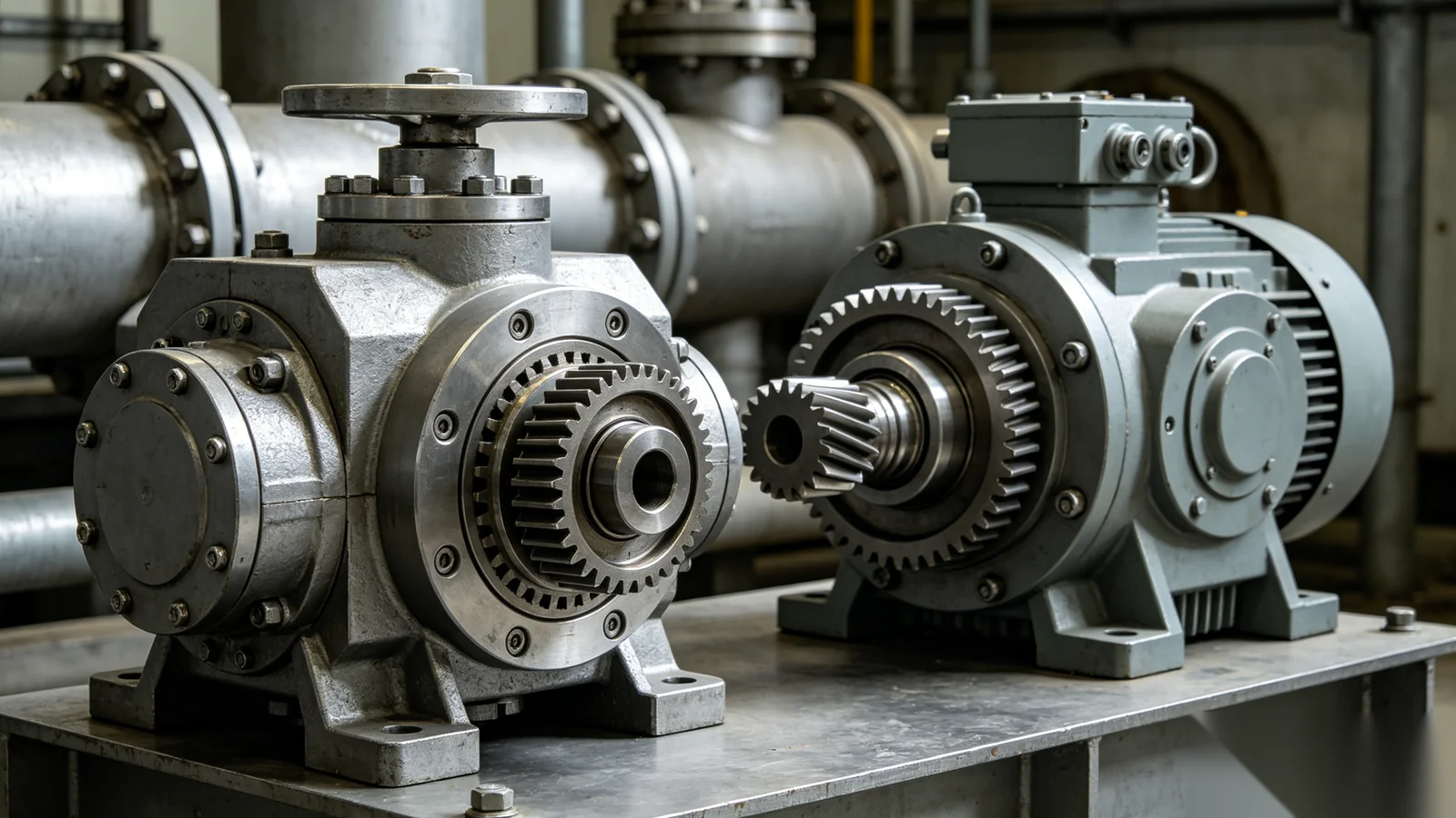
A worm and worm-wheel pair converts low input torque at the handwheel or actuator into high output torque at the valve stem, expressed as a gear ratio. Higher ratios and double-reduction stages raise output torque at the cost of more input turns. The worm thread lead angle determines whether the gearbox is self-locking — a defining safety property for isolation valves that must not creep open under line pressure.
Selection Method
Selecting by torque follows a repeatable sequence: establish valve demand torque, apply a safety factor, then choose a gear ratio that keeps input rim force or actuator torque within limits. Use the matrix below as a starting framework, then submit valve data for calculation.
Bands are qualitative guidance. Required torque is determined by calculation from valve data — no product torque values are implied above.
Apply a safety factor on calculated break torque — commonly between 1.25 and 1.5 depending on project standard, media, and duty cycle. The factor covers seat aging, packing adjustment, and pressure transients. Document the factor and its basis so the selection is auditable from RFQ through submittal.
Configurations
Compact worm operators for small quarter-turn valves and light water duty with direct ISO 5211 mounting.
Standard-ratio worm operators for mid-size butterfly and ball valves with verified rim force and automation margins.
Reinforced housings and higher reduction stages for high-friction seats, large bore, and elevated operating torque.
Ratio selected to balance output torque against number of turns and input rim force or actuator stall rating.
Multi-turn units for rising-stem gate and globe valves; bevel gearing for right-angle input in confined spaces.
Topworks and declutchable override sized so actuator stall torque stays within operator and stem capacity.
Applications
High-torque worm gear operators serve large and high-pressure valves across heavy industry. Selection priorities shift by sector — corrosion resistance for water, pressure-driven torque for oil and gas, large-bore sizing for power, and impact and dust resistance for mining.
Custom Support
When standard torque bands do not cover the application — non-standard stems, combined reductions, or extreme pressure — custom torque gearbox engineering closes the gap with calculation, CAD submittals, and test verification on request. OEM and EPC teams receive revision-controlled drawings and interface exception lists before manufacturing release.
Detailed specifications — output torque, gear ratio, ISO 5211 flange class, drive bush bore, weight, and material grades — are confirmed per project and configuration. Detailed specifications available on request — request a datasheet.
Request a DatasheetShare valve type, size, pressure class, and operating conditions — our application engineers return torque calculations with documented safety factors, recommended gear ratios, and ISO 5211 interface checks. OEM and EPC teams receive CAD submittals and custom torque engineering for applications beyond standard selection matrices.
Common Questions
Start from valve type, bore, seat material, and maximum differential pressure to find break and running torque. Quarter-turn valves peak at unseating; multi-turn valves accumulate stem friction across the stroke. Apply your project safety factor (commonly 1.25 to 1.5) and confirm input rim force or actuator torque stays within limits. Submit stem diameter and operating temperature for a documented calculation.
Most projects apply a safety factor between 1.25 and 1.5 on calculated break torque. The factor compensates for seat aging, packing tightening, pressure transients, and tolerance in published valve torque data. Higher factors suit infrequent safety-critical isolation valves; lower factors suit frequently cycled, well-characterized valves. Record the factor and its basis in the selection documentation.
Yes. Large-diameter and high-pressure valves often require custom torque gearboxes with reinforced housings, multi-stage reduction, and upgraded bearings. Custom engineering covers structural mounting review, bevel-worm combinations, and torque test verification on request. Submit valve drawings and load data so the configuration is confirmed by calculation before manufacture.
Low-torque operators are compact single-reduction worm units for small quarter-turn valves at low differential pressure. High-torque operators use higher reduction ratios, double-reduction stages, reinforced housings, and bearing upgrades for large-bore or high-pressure valves. The correct unit is set by calculated valve demand and safety factor, not by physical size alone.
Yes. Custom torque output, gear ratio, mounting, and material configurations are engineered to project requirements with CAD approval before production. OEM and ODM programs include private-label documentation and locked interface standards. Detailed specifications are confirmed per configuration — request a datasheet for a specific application.